How Do Fishbone Diagrams Solve Manufacturing Problems

ConceptDraw DIAGRAM application extended with Fishbone Diagrams solution lets you construct Fishbone diagrams and represent globally recognized standards for manufacturing 6 Ms and 8 Ms.
Types of Welding in Flowchart

This sample shows the Flowchart that displays the solid-state welding processes, the types of welding.
Flowchart of Products. Flowchart Examples
A Flowchart is a graphically representation of the process that step-by-step lead to the solution the problem. The geometric figures on the Flowchart represent the steps of the process and are connected with arrows that show the sequence of the actions. The Flowcharts are widely used in engineering, architecture, science, analytics, government, politics, business, marketing, manufacturing, administration, etc.
Flowchart Marketing Process. Flowchart Examples

Using the ready-to-use predesigned objects, samples and templates from the Flowcharts Solution for ConceptDraw DIAGRAM you can create your own professional looking Flowchart Diagrams quick and easy.
Cause and Effect Diagrams
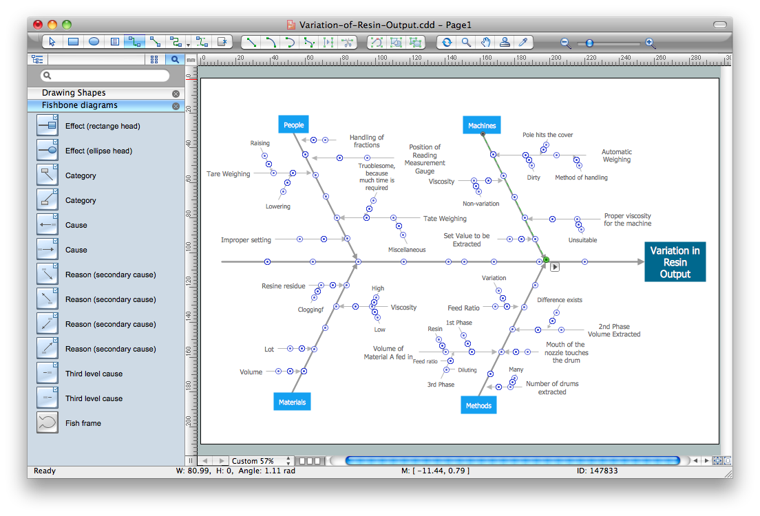
ConceptDraw DIAGRAM powerful diagramming and vector drawing software provides the Fishbone Diagrams solution from the Management area of ConceptDraw Solution Park that allows to design the Cause and Effect Diagrams quick, easy and effective.
Basic Flowchart Symbols and Meaning


Copying Service Process Flowchart. Flowchart Examples
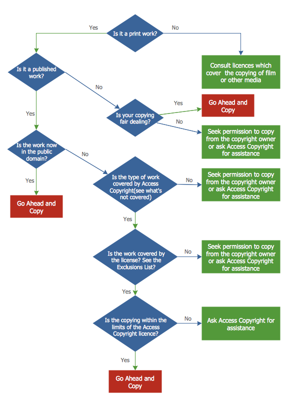
This sample shows the Flowchart on that it is displayed the process of the determination the permissibility according the Access Copyright license. The diamonds represent the decision points. Inside the diamonds are the questions that need the answer yes/no. It is necessary to answer on the question, make the decision that will determine the next step.
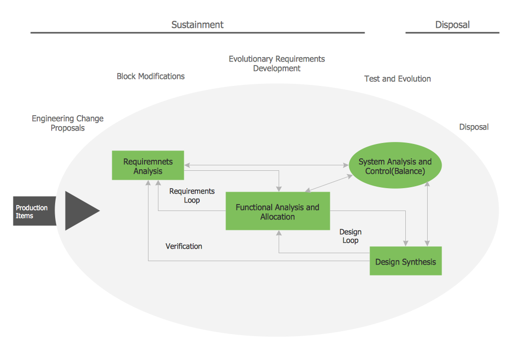
Process Flowchart


Sample Project Flowchart. Flowchart Examples
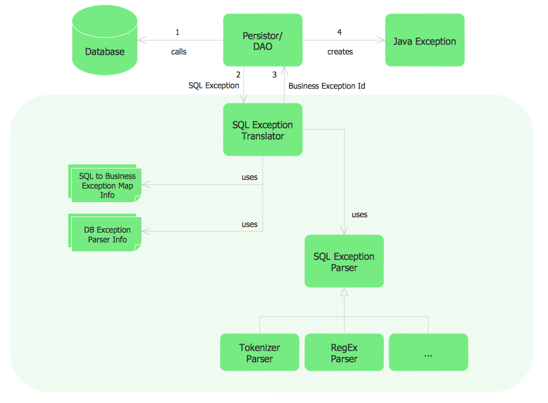
This sample was created in ConceptDraw DIAGRAM diagramming and vector drawing software using the Flowcharts solution from the Diagrams area of ConceptDraw Solution Park.

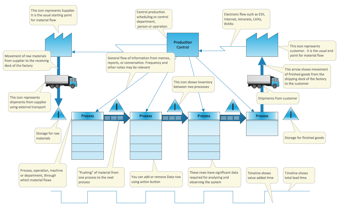
Value Stream Mapping Template
- Quality In Manufacturing Pdf And Ppt
- Production Quality Symbols Pdf
- Manufacturing Quality Symbols Pdf
- Production Process Flow Chart Ppt
- Tqm Pdf Ppt Ms
- Power Point Quality Control Pdf
- Quality Control Pdf Ppt Download
- Quality Control In Manufacturing Ppt
- Manufacturing Of Car Flow Chart Pdf
- Quality Control | Value-Stream Mapping for Manufacturing | Best ...
- ERD | Entity Relationship Diagrams, ERD Software for Mac and Win
- Flowchart | Basic Flowchart Symbols and Meaning
- Flowchart | Flowchart Design - Symbols, Shapes, Stencils and Icons
- Flowchart | Flow Chart Symbols
- Electrical | Electrical Drawing - Wiring and Circuits Schematics
- Flowchart | Common Flowchart Symbols
- Flowchart | Common Flowchart Symbols