Electrical and Telecom Plan Software
Electrical and Telecom Plan Software
Electrical and Telecom Plans is an important part of engineering and architectural projects. Electrical and Telecom Plans are technical drawings that show information about power, lighting, communication and telecommunication. They depict all electrical and telecom details including wires, outlets, circuit panels, etc.
Electrical and Telecom Plans are created and used by architects, engineers, builders, electricians, etc. for the electrical, telecom systems of different buildings, homes, communication centers, power plants, electrical distribution systems, etc. They consist of lines, special symbols, dimensions and notations.
ConceptDraw is a fast way to draw:
- Electrical circuit diagrams
- Electrical wiring diagrams
- Telecom plans
- Schematics
- House electrical plans
- Control wiring diagrams
- Power-riser diagrams
- Cabling layout schemes
- Reflected ceiling plans
- Lighting panels layouts
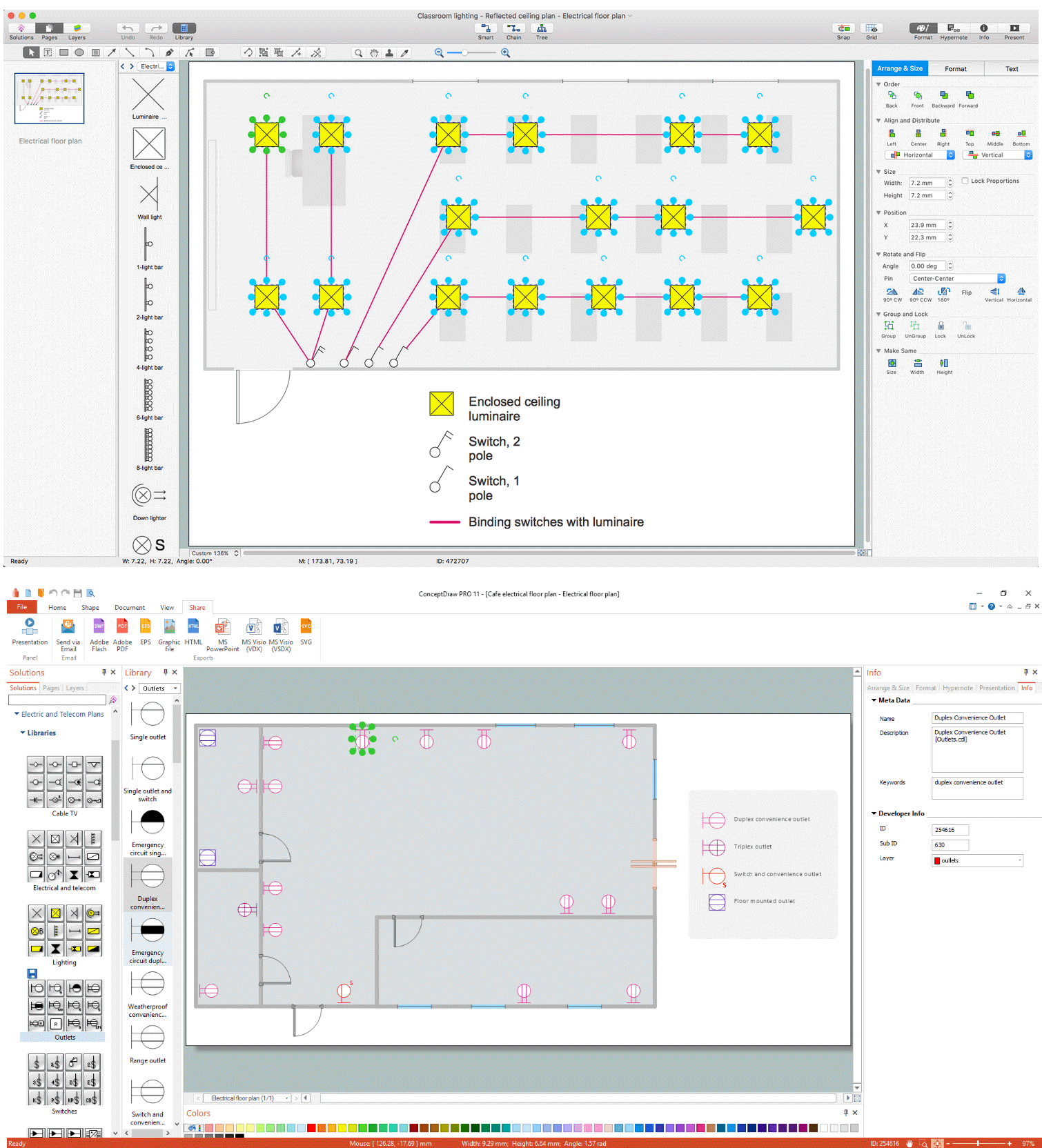
Pic. 1. Electrical and Telecom Plan Software
ConceptDraw DIAGRAM powerful diagramming and vector drawing software provides Electric and Telecom Plans solution that allows draw Electrical and Telecom Plans quick, easy and effective.
Electrical and Telecom Symbols

Pic. 2. Electrical and Telecom Symbols
Electrical and Telecom library of Electric and Telecom Plans solution contains a large number of predesigned vector symbols of electrical and telecommunication equipment. You can simply drop them into your document to design professional looking Electrical and Telecom Plans.
Electrical and Telecom Design House Plan Example
Electric and Telecom Plans solution also includes collection of examples and templates that you can use and change for your needs.

Pic. 3. Electrical and Telecom Design House Plan Example
This example was created in ConceptDraw DIAGRAM using the Electric and Telecom Plans solution from the Building Plans area of ConceptDraw Solution Park. It shows the Electrical and Telecom Design Plan of the house.
The Electrical and Telecom Plans produced with ConceptDraw DIAGRAM are vector graphic documents and are available for reviewing, modifying, converting to a variety of formats (image, HTML, PDF file, MS PowerPoint Presentation, Adobe Flash or MS Visio), printing and send via e-mail in one moment.
TEN RELATED HOW TO's:
The efficiency of any corporate network depends on many factors such as equipment, architecture etc. Moreover, every administer knows that network architecture is a cornerstone for any system. Also, it's easy to make a draft of a network structure using an appropriate diagramming tool.
Designing network architecture diagrams refers to the network structure, including hardware, software, connectivity, protocols of communication and type of transmission: wired or wireless. A high performance, highly reliable, and secure network architecture is critical for the successful deployment and operation of modern communication network. This diagram represents in detail the sample of the network architecture of the three-divisional office. It is designed using vector libraries supplied with ConceptDraw Computer and Networks solution.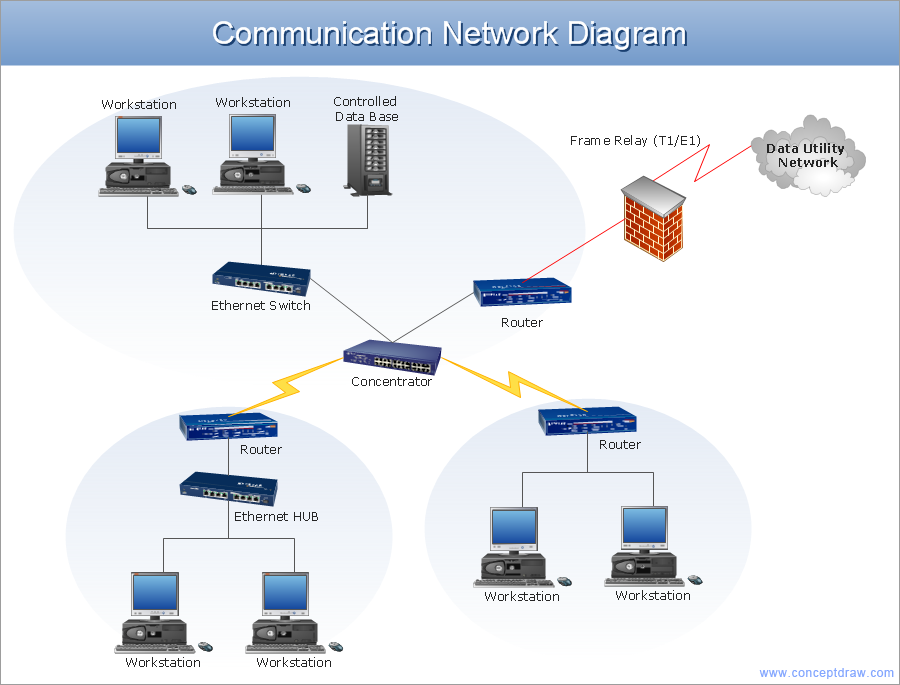
Picture: Network Architecture
Related Solution:
Electronic components have two or more electrical terminals (or leads) aside from antennas which may only have one terminal. These leads connect to create an electronic circuit with a particular function (for example an amplifier, radio receiver, or oscillator). Basic electronic components may be packaged discretely, as arrays or networks of like components, or integrated inside of packages such as semiconductor integrated circuits, hybrid integrated circuits, or thick film devices.
26 libraries of the Electrical Engineering Solution of ConceptDraw DIAGRAM make your electrical diagramming simple, efficient, and effective. You can simply and quickly drop the ready-to-use objects from libraries into your document to create the electrical diagram.
Picture: Electrical Symbols — Composite Assemblies
Related Solution:
UML Class Diagrams describes the structure of a system by showing the system's classes, their attributes, and the relationships among the classes.
Picture: UML Class Diagram. Design Elements
Related Solution:
Engineering students usually have huge amount of homework. Learning how to develop a technical drawing is one of the necessary skills. Luckily, at the present time, there’s no need to draw it on paper, because there a lot of software tools for it.
This drawing represents the Bearing symbols library, that is the part of the ConceptDraw Mechanical Engineering solution. Bearings are the important components of any movable mechanism. The function of bearing is to align, guide, and support the moving parts in any mechanical construction. Usually they are located between moving and stationary parts, it works as a connection point between them. Using Mechanical Engineering solution and ConceptDraw DIAGRAM one can effortlessly draw engineering diagrams of any complexity.
Picture: Technical Drawing Software
Related Solution:
A circuit diagram or wiring diagram uses symbols to represent parts of a circuit.
Electrical and electronic circuits can be complicated. Making a drawing of the connections to all the component parts in the circuit's load makes it easier to understand how circuit components are connected. Drawings for electronic circuits are called "circuit diagrams". Drawings for electrical circuits are called "wiring diagrams".
26 libraries of the Electrical Engineering Solution of ConceptDraw DIAGRAM make your electrical diagramming simple, efficient, and effective. You can simply and quickly drop the ready-to-use objects from libraries into your document to create the electrical diagram.
Picture: Electrical Symbols — Electrical Circuits
Related Solution:
Infrastructure is very important part of any district, and educational buildings presence is one of the factors. Another not less important thing is the school design, because it influences the children's’ sense of aesthetics. To develop a harmonic school layout, use a proper software.
This image represents the School layout library that is supplied with ConceptDraw School and Training Plans solution. The library contains a set of vector graphic objects that will be in help while drawing a layout of classroom. Any lecturer desires to organize the layout of the classroom for the best student advantage. Students must be focused and be engaged in the learning process. The classroom places organization is an important element of a students learning. It is significant for a lecturer to set up a classroom layout and change it time to time to support lectures, to invoke disputes or solve any organizational issues. By using ConceptDraw DIAGRAM you can easily plan how to re-arrange the desks in the class room to maintain visual control of your class and build a friendly environment in the classroom.
Picture: Building Drawing Software for Design School Layout
Related Solution:
ConceptDraw MINDMAP is effective Mind Mapping Software with rich clipart galleries, extensive drawing capabilities, a large quantity of examples of professionally designed mind maps on the different themes and powerful import and export capabilities.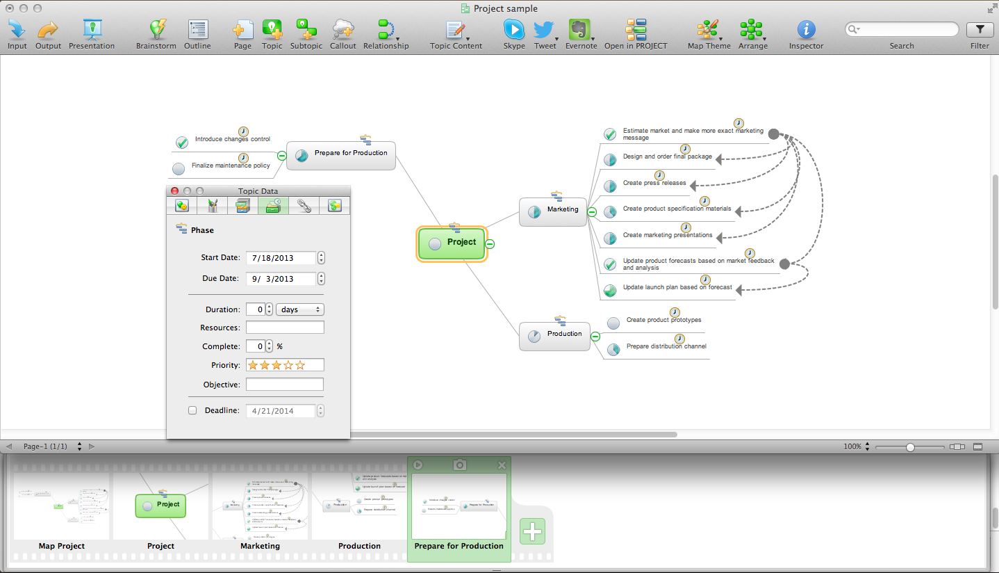
Picture: Mind Mapping Software
Related Solution:

