Ring Network Topology
Ring Network Topology Diagram
A network topology in which each of the nodes connects to two other nodes, resulting in forming a continuous pathway for the signals through each of the nodes known to be called the “rings”, is known to be called as a “ring network”. Data within such networks is known to be traveling from one node to another node, through all the nodes one by one along its way handling every single packet. The mentioned “rings” can be “unidirectional”, having all its traffic travelling clockwise or anticlockwise all the way around the ring. Also, it can be the so called “bidirectional”, providing only one single pathway between two nodes out of many other nodes. A unidirectional ring network is known to be very likely disrupted by the failure of some link appearing to be nearby.
A node failure as well as any cable break may lead to isolation of every single node, which is attached to the “ring”. Some of the ring networks are known to be adding a so called "counter-rotating ring", also known to be called a “C-Ring”. Adding the mentioned ring can be done for forming a redundant topology. Thus, once break happens, a data may get wrapped back on the ring before it reaches the end of the cable. Such data is known to be maintaining a path to every single node all the way along the resulting counter-rotating ring.
The "dual ring" networks are known to be including the so called “Spatial Reuse Protocol”, as well as the “Fiber Distributed Data Interface”, or “FDDI”, and the “Resilient Packet Ring”. The well-known “IBM token ring networks” are also sometimes called as the “802.5 networks”. They are commonly used for avoiding all the possible and existing weakness of a ring topology by using another topology — a “star” one. Such mentioned topology is usually used at the physical layer for imitating a ring at the so called “data link layer”.
Some of the previously mentioned “SONET/SDH rings” have two sets of the bidirectional links, which can be found between the nodes, allowing the failures or maintenance at the multiple points of the same ring resulting in no loss of the primary traffic on the outer ring in a way of switching the traffic on the inner ring after the so called “failure points”.
One of the advantages of using such network topology can be mentioned the convenience of using it for performing in a better way than a bus topology does, especially in the cases of the need of loading under the so called “heavy network”. The mentioned network topology is known to be used within a very orderly network having every device accessing to the “token” having the opportunity to transmit. Such ring network topologies do not require any central nodes for managing the connectivity between different computers. Because of such point to point line configuration of devices with a device on another side, it is quite simple to install as well as to re-configure whatever is needed by removing or adding any device.
Another special feature of the ring network topologies is its “point to point” line configuration, which makes it much simpler to isolate all the previously identified faults. Also, the reconfiguration for line faults of bidirectional rings in ring network topology can be very fast, having all the switching happening at the highest level, leading to the traffic not requiring any individual re-routing.
The disadvantages of the ring network topology: first of all, it is always more difficult to configure using it to compare to using a “star” one as any node adjunction equals to the ring reconfiguration and shutdown. One of the malfunctioning workstations within the ring network topology can create lots of problems for all the network. This can be solved by using a switch or a dual ring used for closing off the break. Every time there’s some moving, changing and adding the devices can affect the entire ring network and the communication delay is known to be directly proportional to the number of all the existing nodes in the ring network.
It is important to remember that any ring network may afford the so called “fault tolerance” to the telecommunication network having two paths between any two nodes on the network. Ring protection is known to be a system commonly used for assuring any needed communications, continuing in the event of failure of only one path. The most widely used protection architectures are “1+1” as well as “1:1”.
In 1+1 architecture, every single protection path is known to be used for protecting the signal having the bridge at the head of the path on a permanent basis, while the switching occurs at its tail end. There are more than two parallel routes are sent in this architecture traffic and the receiving end is known to be selecting the better of the mentioned two signals. Once some failure occurs, the destination switches into one of the alternative paths. The mentioned architecture is quite a widely used for as it is simple for implementing, resulting quite fast restoration. Although, there’s still a drawback, which is the wastage of the bandwidth, occurring for a reason of no traffic traveling through the redundant path.

Pic. 1. Ring Network Topology
Drawing the ring network topology diagrams taking into consideration any of the mentioned architectures can be always much simpler using a professional software for completing such tasks. One of the best applications nowadays is ConceptDraw DIAGRAM one, enabling all its users to create a great looking diagram, such as a ring network topology one, especially having the Computer and Networks solution downloaded from ConceptDraw STORE application.

Pic. 2. Ring Network Topology Diagram
Having the ConceptDraw DIAGRAM software means having all the needed tools for making smart looking drawings, at the same time having the ConceptDraw STORE which is meant to be used while working in ConceptDraw DIAGRAM means simplifying your work with creating such diagrams by using the previously developed solutions full of the stencil libraries with the design symbols depending on the subject of your drawing.
See Also Network Topologies:
- Bus Network Topology
- Star Network Topology
- Mesh Network Topology
- Tree Network Topology
- Fully Connected Network Topology
TEN RELATED HOW TO's:Electronic components have two or more electrical terminals (or leads) aside from antennas which may only have one terminal. These leads connect to create an electronic circuit with a particular function (for example an amplifier, radio receiver, or oscillator). Basic electronic components may be packaged discretely, as arrays or networks of like components, or integrated inside of packages such as semiconductor integrated circuits, hybrid integrated circuits, or thick film devices. 26 libraries of the Electrical Engineering Solution of ConceptDraw DIAGRAM make your electrical diagramming simple, efficient, and effective. You can simply and quickly drop the ready-to-use objects from libraries into your document to create the electrical diagram. Picture: Electrical Symbols — Composite AssembliesRelated Solution:ConceptDraw DIAGRAM is a powerful Network Engineering software thanks to the Vehicular Networking Solution and many other networking solutions from the Computer and Networks Area of ConceptDraw Solution Park.
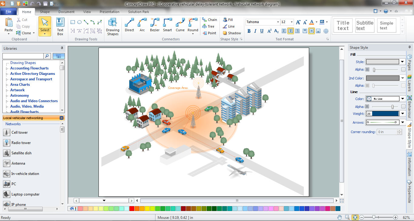 Picture: Network EngineeringRelated Solution:The ConceptDraw vector stencils library Cisco Telepresence contains videoconference equipment symbols for drawing the computer network diagrams.
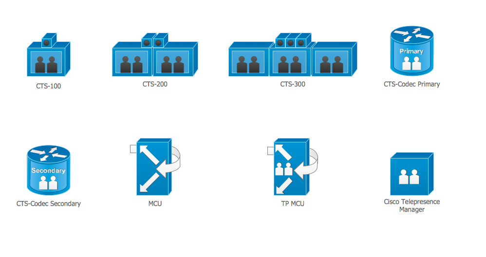 Picture: Cisco Telepresence. Cisco icons, shapes, stencils and symbolsRelated Solution:Energy Pyramid Diagram is a visual graphical representation of the biomass productivity on the each trophic level in a given ecosystem. Its designing in ConceptDraw DIAGRAM will not take much time thanks to the unique Pyramid Diagrams solution from the Marketing area of ConceptDraw Solution Park. Energy Pyramid Diagram begins from the producers (plants) and proceeds through a few trophic levels of consumers (herbivores which eat these plants, the carnivores which eat these herbivores, then carnivores which eat those carnivores, and so on) to the top of the food chain.
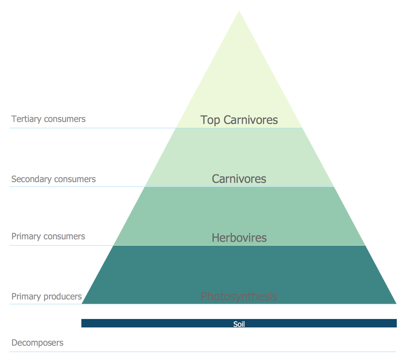 Picture: Energy Pyramid DiagramRelated Solution:An Enterprise private network (EPN) is a computer network built by an enterprise to interconnect the sites of the company (such as head and remote offices, shops, production sites, etc.) on purpose to share the computer resources. This example was created in ConceptDraw DIAGRAM using the Computer and Networks solution from the Computer and Networks area of ConceptDraw Solution Park. It shows the Enterprise Private Network (EPN) using the frame-relay and dial-up.
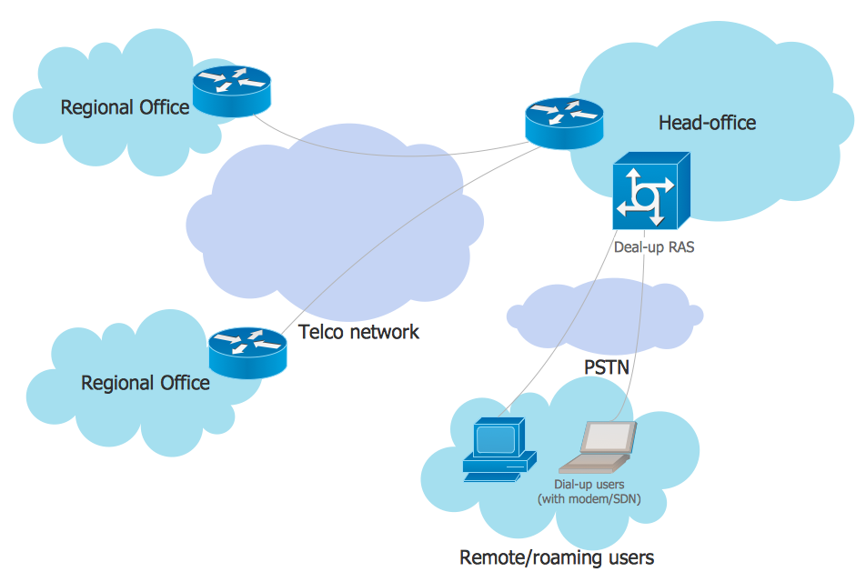 Picture: EPN Frame-Relay and Dial-up Network. Computer and Network ExamplesRelated Solution:A Telecommunications network is a network of nodes, links, trunks and telephone switches that are connected, operated by telephone companies and realize telephone, audio, visual and data communications among the users. The telecommunications network can also include Internet, microwave, wireless equipment. This example was created in ConceptDraw DIAGRAM using the Computer and Networks Area of ConceptDraw Solution Park and shows the Telecommunications network.
 Picture: Telecommunication networks. Computer and Network ExamplesRelated Solution:ConceptDraw DIAGRAM diagramming and vector drawing software extended with Chemistry solution from the Science and Education area of ConceptDraw Solution Park is effective for drawing various organic chemistry schemes, diagrams, illustrations thanks to the included collection of predesigned organic chemistry symbols.
 Picture: Organic Chemistry SymbolsRelated Solution:The use of the special software with Plant Design Solutions is a real help for effective creating the Plant Plan, Plant Layout Plan, Process Plant Layout, Plant Design. ConceptDraw DIAGRAM is the best diagramming and vector drawing software. It offers the Plant Layout Plans Solution from the Building Plans Area for achievement this goal.
 Picture: Plant Design SolutionsRelated Solution:ConceptDrawDIAGRAM 17